
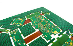
flex pcb board
A flex circuit board is an electrical printed circuit board that can bend and twist to fit the contours of the product it will be installed in. It is also more resilient than rigid PCBs, so it can be used in products that undergo frequent movement. It saves time and money for assembly and testing by eliminating the need to connect wires with soldering. It is a good choice for small electronic devices and wearables that require high reliability. It is a cost-effective alternative to custom molding and other expensive solutions.
To make a flex pcb board, the first step is to create a schematic and layout. A PCB layout is a document that shows the position of each component on a board. It includes dimensions, connections, and pins. It also includes the type and location of signals, currents, and voltages. It can be created using a computer program or manually by tracing a design with a pencil. Once the layout is complete, it should be checked for errors by an engineer or a professional PCB designer.
The next step is to identify the specific mechanical requirements for a flex pcb board. The design should be made for both static and dynamic flex regions. This can be done with industry-standard ECAD/MCAD tools that offer a comprehensive toolkit for designing flex and rigid-flex PCBs. The flex layer should be placed inside the stack-up to protect it from outer-layer plating and improve impedance control.
How to flex pcb board
Other considerations include selecting the proper flex material, pad thickness, and pad fillets. Pad fillets help improve etch yield and strength, and they are appropriate when the pad diameter is larger than connecting traces. A tear guard is also helpful in preventing tears in a flex circuit. It can be created by adding a relief hole or large corner radius.
Another important consideration is the operating environment. The flex circuit should be designed to withstand the environmental stresses that can cause stress cracking in copper traces. It is also important to consider the bending ratio for the flex region and choose the right materials based on this information. The flex material should be thin enough to provide adequate conductor length and flexibility. Conductors should be routed through the bend area as close to perpendicular as possible to minimize stress on the copper.
It is recommended to use the same manufacturing steps for a flex circuit as a rigid PCB, which will reduce costs. This includes selecting the right materials and using the same processes. It is also important to select a turnkey manufacturer that offers engineering, fabrication, and assembly services at one facility. This will prevent multivendor miscommunication and ensure consistent quality. The manufacturer should have advanced equipment and be ISO 9001 and AS9100C certified. They should also have a physical location and showroom to show off their capabilities.